
EEE, ECE & IE Project Updates
EEE, ECE & IE Project Updates |  |
| Posted: 18 Jun 2014 06:15 AM PDT This circuit simulates the police car lights by alternate flashing. This circuit flashes red LEDs for three times and blue LED's for three times. This flashing action performs continuously. This circuit uses 555 timer and a decade counter. Here, 555 timer runs in astable mode. Decade counter 4017 counts the incoming pulses that is for first pulse Q0 becomes high and for second pulse Q1 becomes high and so on again for 10th pulse Q0 state becomes high. 555 Timer Based Police Lights Circuit Principle:Here 555 timer produces continuous pulses via pin 3. The width of these pulses can be varied by varying the resistance (R1,R2 ) or capacitance (C1). These pulses are given as input to the decade counter. For every incoming pulse the output state of the decade counter is get incremented.
Hence red LEDs flash for 3 times. This process repeats continuously. Circuit Diagram of Police Lights using 555 Timer: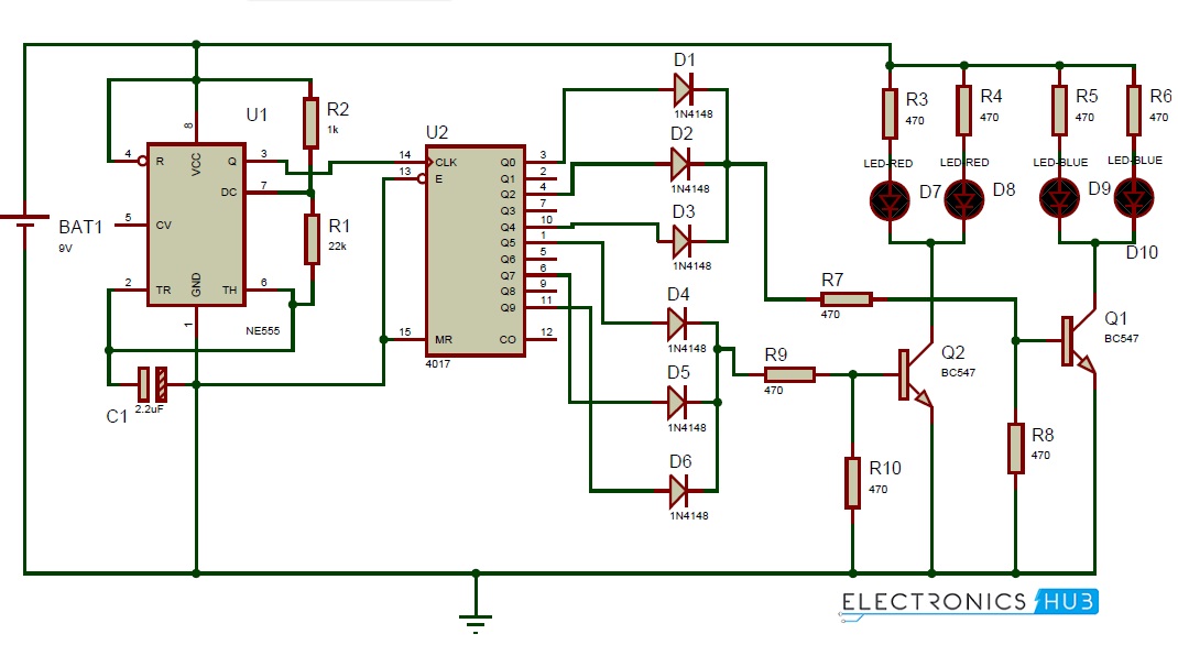 Circuit Diagram of Police Lights using 555 Timer Circuit Components:
555 Timer based Police Lights Circuit Design:555 Timer: Here 555 timer runs in free running mode. It produces pulses whose width can be varied. 2nd and 6th pins are shorted to allow triggering after every cycle. 4th pin is connected to Vcc to avoid sudden resets. 4017 Decade Counter: It is a 10 bit counter with ten decoded outputs. It counts the incoming pulses. The supply voltage range is -0.5 to +22V. The high pulse on the reset pin clears the count to zero. The speed of operation of this IC is up to 10 Mhz. The ouput states (Q0,Q2,Q4) are ORed to flash the blue LED's 3 times and the states Q5, Q7 and Q9 are ORed to flash the red LED's 3 times. Based on the outputs of 4017 IC, two transistors (NPN) switches the LED's ON and OFF. Resistors R3, R4, R5, R6 are used to protect the LED's from high voltage. How to Operate Police Lights Circuit:
555 Timer based Police Lights Circuit Applications:
Limitations of Police Lights Circuit:
The post Police Lights using 555 Timer appeared first on Electronics Hub. |
| Posted: 18 Jun 2014 02:32 AM PDT Nowadays LED lights are increasing rapidly because of their reduced cost and long durability. Generally, one can see the LED lights increasing and decreasing their intensities depending on the number of persons entering or leaving at a particular place or a room. It depends on the fading of LEDs. Here is a simple circuit that slowly fades out when it is applied with some voltage. This article explains the circuit that starts fading depending on the incoming voltage. UP/DOWN Fading LED Lights Circuit Principle:The circuit mainly consists of a transistor and a capacitor. Light Emitting Diode conducts in forward bias condition i.e. LED glows only when positive terminal is connected to the positive end and negative end is connected to the negative of the battery. In this proposed circuit, LED conducts only when the negative terminal is grounded as the positive terminal is applied with some voltage. When the button is pressed, the capacitor starts charging and discharging which causes the LED to fade up and down.
UP/DOWN Fading LED Lights Circuit Diagram: Up-Down Fading LED Lights Circuit Diagram Circuit Components:
UP/DOWN Fading LED Lights Circuit Design:In this circuit, the power supply is connected to the On/Off switch. A 10k resistor is connected after the button to bring the button to the pull down mode. This makes the button initially low and when it is pressed, it becomes high. Switch is connected to a diode PN junction diode 1N 4007. Diode allows conducting in forward bias condition only. Diode is then connected to a resistor of resistance 330K, which is in series to another resistor of 60kOhms. Another resistor of 36k ohms is connected before the transistor for protection. Transistor used here is a NPN transistor of series BC547. This NPN transistor is initially in off state i.e. it will not conduct. Voltage from emitter to collector flows, only if the base region is applied with some voltage. The minimum voltage required at the base of the transistor is 0.7v. When this voltage is applied, transistor breakdown occurs and voltage starts flow from emitter to collector. You may get more knowledge on NPN Transistor by reading the post – Transistor Biasing and Characteristics
Capacitor is connected in series to the resistor of 60K. The capacitor used is 220uf and 16v rated electrolytic capacitor. This capacitor is required for producing pulses to On/Off the LED. How UP/DOWN Fading LED Lights Circuit Working?
Applications of UP/DOWN Fading LED Lights Circuit:
Limitations of the Circuit:
The post UP/DOWN Fading LED Lights appeared first on Electronics Hub. |
| You are subscribed to email updates from Electronics Hub To stop receiving these emails, you may unsubscribe now. | Email delivery powered by Google |
| Google Inc., 20 West Kinzie, Chicago IL USA 60610 | |


