
EEE, ECE & IE Project Updates
EEE, ECE & IE Project Updates |  |
| Posted: 02 Jul 2014 09:27 PM PDT CAUTION: Before going to explain about this concept, we are going to strictly suggesting that DON’T TRY TO IMPLEMENT IT PRACTICALLY AS IT PRODUCES VERY HIGH VOLTAGE. A stun gun is a gadget used to produce a high voltage, low current signal, used mostly as a weapon to stun or send shock waves to the target with the intention to weaken or paralyze it. However proceeding to design the circuit, it should be kept in mind that in some countries, stun gun is banned. Because, this is actually a lethal weapon which can render a person mentally paralyzed. It is usually powered by a 9V battery. Here, we design a stun gun circuit using a 555 Timer to produce a current fluctuating signal and a voltage multiplier using a transformer and a multiple stage arrangement of voltage doublers using capacitors and diodes. Stun Gun Circuit Operating Principle:The stun gun circuit is based on the principle behind a conventional stun gun. A 555 Timer is used to produce an oscillating signal of frequency determined by the external passive elements connected to the Timer. These low current electric pulses are fed to a step up transformer to produce a high volt signal, which is further increased by a voltage multiplier circuit. The voltage multiplier circuit consists of multiple stages of voltage doubler each consisting of two diodes and two capacitors. The voltage doubler circuits are based on Villard doubler method. Output voltage is directly proportional to the number of stages. Stun Gun Circuit Diagram: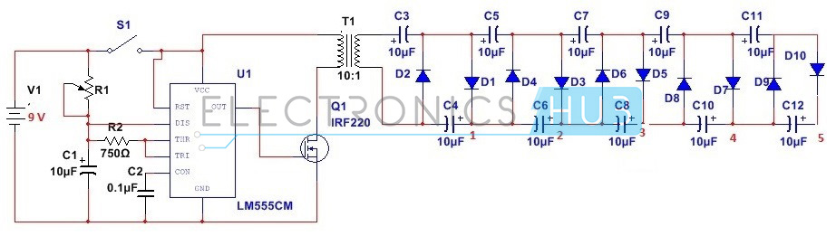 Circuit Diagram of Stun Gun Stun Gun Circuit Design:Actually, here we require two phases of designing – The astable multivibrator design and voltage multiplier design. Designing the circuit requires pioneer step of deciding the output voltage . Here our requirement is to generate a 10KV DC voltage from 1000V input. From the equation, Vout = (2Vin + 1.414)S, where S is the number of stages. To obtain voltage of 10KV, about 5 stages of voltage doubler would be required. Here we design a 5 stage voltage multiplier circuit generating an output voltage of 10KV. Since input voltage is around 1000v, each capacitor should have a voltage rating of atleast 1000V. Since here operating frequency is low, of the order of Hertz, we require a 2500V, 10mF. For designing the astable multivibrator circuit, we select a 555 Timer. To design a 555 Timer in astable mode, passive external components need to be selected. Assuming a maximum operating frequency of 50Hz and a duty cycle of 75%, we calculate R1 to be around 1.44K, R2 around 720 Ohms and C1 around 10uF. Here we select a 2K potentiometer, 720 ohm resistor and 10uF capacitor. Since this is a low frequency operation, a MOSFET IRF530 is used.
How to Operate Stun Gun Circuit?As soon as the switch S1 is pressed, the astable operation of 555 Timer starts. A pulsating electric signal of low current is produced, which is stepped up using a step up transformer, to a voltage of around 1000V. The signal from the Timer is fed through a MOSFET switch.
Stun Gun Applications:
Limitations of Stun Gun Circuit:
The post Stun Gun Circuit appeared first on Electronics Hub. |
| Interfacing DC Motor with 8051 Microcontroller Posted: 02 Jul 2014 08:57 PM PDT When we talk about controlling the robot, the first thing comes into the mind is controlling DC motors. Interfacing DC motor to the microcontroller is very important concept in Robotic applications. By interfacing DC motor to the microcontroller, we can do many things like controlling the direction of the motor, controlling the speed of the motor. This article describes you how to control the DC motor using AT89C51 controller. Interfacing DC Motor to 8051 Circuit Principle:The maximum output current of microcontroller pin is 15mA at 5V. But the power requirements of most of DC motors is out of reach of the microcontroller and even the back emf (electro motive force) which is produced by the motor may damage the microcontroller. Hence it is not good to interface DC motor directly to the controller. So use motor driver circuit in between of DC motor and controller.
Here, we are using L293D motor driver IC to drive DC motors. Using this IC, we can drive 2 DC motors at a time. For this IC motor supply is variable 4.5 to 36V and it provides maximum current of 600mA. Circuit Diagram of Interfacing DC motor to 8051 Microcontroller: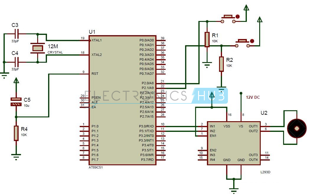 Circuit Diagram of Interfacing DC motor to 8051 Microcontroller Circuit Components:
Interfacing DC Motor to 8051 Circuit Design:The major components in the above circuit diagram are at89c51 microcontroller and motor driver. Here the motor driver input pins IN1, IN2 are connected to the P3.0 and P3.1 respectively to control the motor directions. DC motor is connected to output terminals of L293D. EN1 pin is connected to the 5V DC to drive the motor. Switches are connected to the P2.0 and P2.1 in pull down configuration. First switch rotates the motor in clockwise direction and second switch rotates the motor in anti clockwise direction. 8th pin of motor driver is connected to the battery directly. L293D Motor Driver:L293D is a quadruple H- bridge motor driver, as the name suggests it used to drive the DC motors. This IC works based on the concept of H- Bridge. H-bridge is a circuit which allows the voltage in either direction to control the motor direction. There are 4 input pins for L293D. Motors directions depends on the logic inputs applied at this pins. EN1 and EN2 must be high to drive the 2 DC motors. 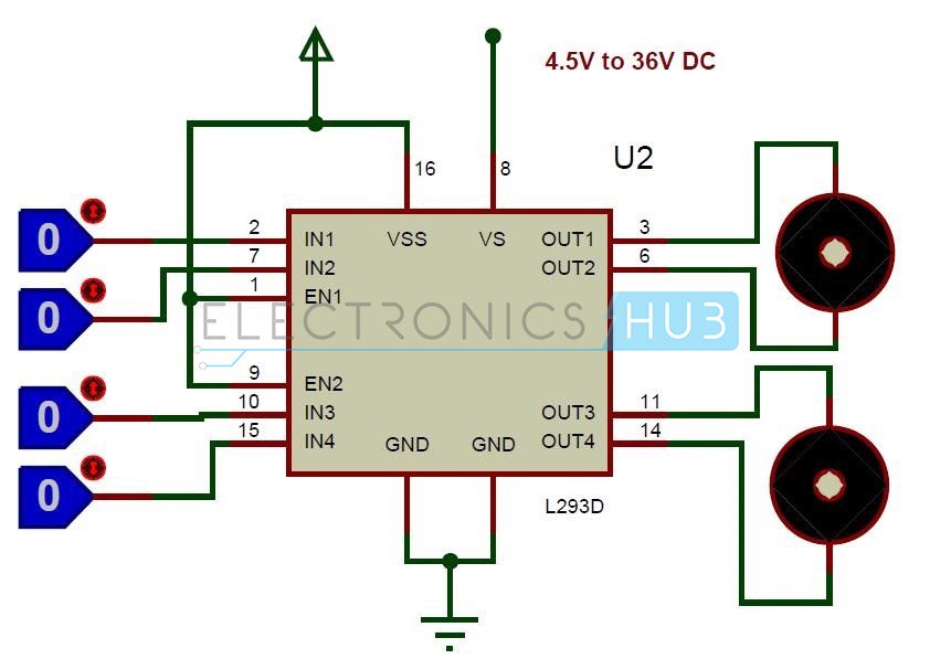 L293D Circuit
Algorithm for Interfacing DC Motor to 8051:
How to Operate the Circuit Interfacing DC Motor to 8051?
Interfacing DC Motor to 8051 Applications:
The post Interfacing DC Motor with 8051 Microcontroller appeared first on Electronics Hub. |
| You are subscribed to email updates from Electronics Hub To stop receiving these emails, you may unsubscribe now. | Email delivery powered by Google |
| Google Inc., 20 West Kinzie, Chicago IL USA 60610 | |


