
EEE, ECE & IE Project Updates
EEE, ECE & IE Project Updates |  |
- Interfacing 7 Segment Display to 8051
- Delay using 8051 Timers
- Frequency Counter Circuit
- Stepper Motor Control using 8051 Microcontroller
| Interfacing 7 Segment Display to 8051 Posted: 01 Jul 2014 06:30 AM PDT Seven segment displays are used to indicate numerical information. Seven segments display can display digits from 0 to 9 and even we can display few characters like A, b, C, H, E, e, F etc. These are very popular and have many more applications. This article describes you how to interface seven segments to AT89C51 microcontroller. This system displays the digits from 0 to 9 continuously with a predefined delay. Interfacing 7 Segment Display to 8051 Circuit Principle:Seven segment displays internally consist of 8 LEDs. In these LEDs, 7 LEDs are used to indicate the digits 0 to 9 and single LED is used for indicating decimal point. Generally seven segments are two types, one is common cathode and the other is common anode.
In common cathode, all the cathodes of LEDs are tied together and labeled as com. and the anode are left alone. In common anode, seven segment display all the anodes are tied together and cathodes are left freely. Below figure shows the internal connections of seven segment Display. 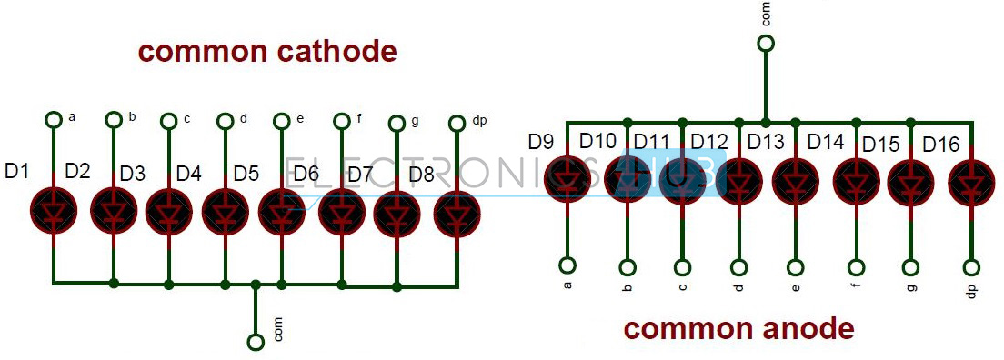 Internal Connections of Seven Segment Interfacing 7 Segment Display to 8051 Circuit Diagram: Circuit Diagram of Interfacing 7 Segment Display to 8051 Microcontroller Circuit Components:
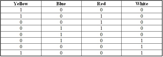
Interfacing 7 Segment Display to 8051 Circuit Design:Here, common cathode seven segment is used to display the digits. In this circuit, pins a to h of the 7 segment are connected to the PORT 2 of the microcontroller and com pin is connected to the ground through the 330 ohm resistor. This resistor is used to drop the voltage. Since we are using common cathode seven segment we need to send LOGIC 1 to the segments to glow. Figure shows structure of common cathode seven segments. Here dot is used for indicating the decimal point. Here all the cathodes of LED's are connected to the Gnd pin. The operating voltage of this LED's is 2 to 3V but from controller we will get 5V so to drop the remaining voltage we have to connect a to g pins to the controller through the resistor. 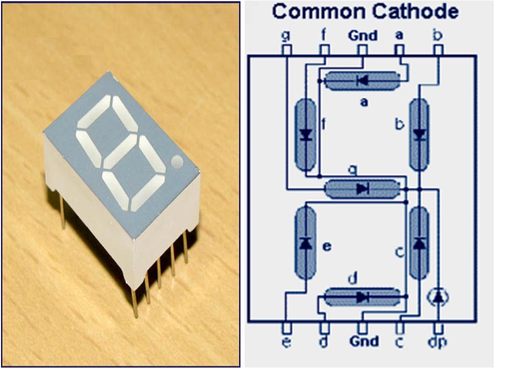 Common cathode 7 segment Display Digit Drive Pattern: To display the digits on 7 segment, we need to glow different logic combinations of segments. For example if you want to display the digit 3 on seven segment then you need to glow the segments a, b, c, d and g. The below table show you the Hex decimal values what we need to send from PORT2 to Display the digits from 0 to 9. Algorithm:
unsigned char arr[10]={0x3f,0×06,0x5b,0x4f,0×66,0x6d,0x7d,0×07,0x7f,0×67};
for (i=0;i<10;i++) { P2=arr[i]; delay_ms(500); } How to Operate Interfacing 7 Segment Display to 8051 Circuit?
Interfacing 7 Segment Display to 8051 Circuit Applications:
Limitations of the Circuit:
The post Interfacing 7 Segment Display to 8051 appeared first on Electronics Hub. | ||||||||||||||||||||||||||||||||||||||||||||||||||||||||||||||||||||||||||||||||||||||||||||||||||||||||||||||
| Posted: 01 Jul 2014 05:15 AM PDT Generation of time delay is most important concept in embedded systems. Most of the times, we need to generate precise time delay between two actions in controller applications. We can generate the time delay using the techniques like LOOP or by using in built delay functions. But these are not precise methods for generating time delay so that we will go for timers to produce accurate time delay. This concept is similar to Time Delay Relay concept. Delay using 8051 Timers Circuit Principle:Most of the controllers have inbuilt timers. These timers are not only used for generating time delay but also used for counting purpose. The value of the counter is incremented by 1 when action or event occurs. Timers in a microcontroller are controlled by the SFRs (Special Function Registers). Timers in different mode of operations are configured by special function registers. Delay using 8051 Timers Circuit Diagram: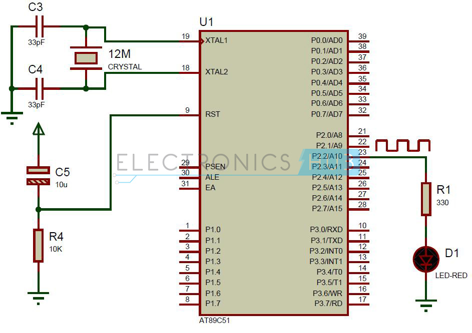 Delay using 8051 Timer Circuit Diagram Circuit Components:
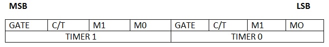
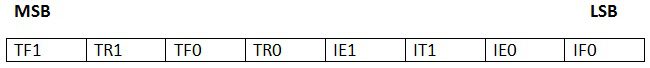
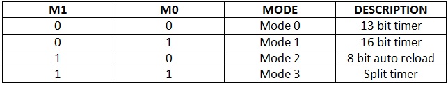
Delay using 8051 Timers Circuit Design:The major component in this circuit is AT89C51 controller. LED is connected to the P2.2 through the 330 ohm resistor to indicate the time delay. 8051 Timers Register Description: TMOD Register: The upper nibble (TMOD.7 to TMOD.4) is used to configure timer1 and the lower nibble (TMOD.3 to TMOD.0) is used to configure timer0. GATE: If this pin is high, then corresponding timer is enabled when there is an interrupt at corresponding INT pin of the microcontroller. C/T: This pin is used to select timer or counter. If this pin is high, then used as a counter to count the external event. If this pin is low, then used as a timer to produce time delay. M1 and M0: These bits are used to select the different timer modes. 13 Bit Timer: This mode uses 8 bits from high byte and remaining 5 bits from low byte. The value of the timer in this mode is from 0000H to 1FFFH 16 Bit Timer: This mode is most commonly used for producing the time delay. In this mode all the 16 bits are used for timer and values vary from 0000H to FFFFH. If the value XXXXH is loaded into the timer register, then the produced time delay is equal to the [(FFFFH – XXXXH+1)*(period of one clock pulse)]. The time period of one clock pulse is equal to the 1.085us 11.0592 MHz frequency. 8-bit Auto Reload: In this mode, initial value is loaded in to the high byte and the same value is loaded into the low byte. Timer value is from 00H to FFH. This mode is used to set the baud rates for serial communication. Split Mode: In this mode timer is divided in to two 8 bit timers. These 8 bit timers can count from 00H to FFH. This mode is used in the applications where we require an additional 8 bit timer or counter. TCON Register: It is a special function register used to control the timer operation. In this register only upper nibble is used to control the timer and remaining bits are used for interrupt control.
In order to produce time delay accurately,
NNNN=time delay/1.085us
MMMM=65536-NNNN
MMMMd = XXYYh
TH=XXh TL=YYh Delay Function to Generate 1 ms Delay: Void delay () { TMOD = 0×01; // Timer1 mode0 TH0= 0xFC; //initial value for 1ms TL0 = 0×66; TR0 = 1; // timer start while (TF0 == 0); // check overflow condition TR0 = 0; // Stop Timer TF0 = 0; // Clear flag } How to Operate the Delay Circuit using 8051 Timers?
Delay using 8051 Timers Circuit Applications:
The post Delay using 8051 Timers appeared first on Electronics Hub. | ||||||||||||||||||||||||||||||||||||||||||||||||||||||||||||||||||||||||||||||||||||||||||||||||||||||||||||||
| Posted: 01 Jul 2014 03:53 AM PDT A frequency counter is an instrument used to measure the frequency. In scientific terms, frequency is the number of cycles per second in the signal. In terms of a layman, frequency of a signal denotes the rate of occurrence of the signal in certain time. Frequency Counters are basically simple counter systems with a limited time period for counting. Here we design a simple frequency counter system using two timers and two counters. While one of the Timer IC is used to produce clock signals, the other is used to produce the time limited signal of one second.
Frequency Counter Circuit Operating Principle:This circuit is based on the simple definition of frequency, which is the number of cycles per second. An astable multivibrator is used to generate oscillating pulses which are fed as clock pulses to a counter. Another monostable multivibrator is used to generate a timing signal for 1 second used to control the counter. The counter thus counts the number of pulses for 1 second and the resultant value displayed on the 7-segment display is the value of frequency in hertz. Frequency Counter Circuit Diagram: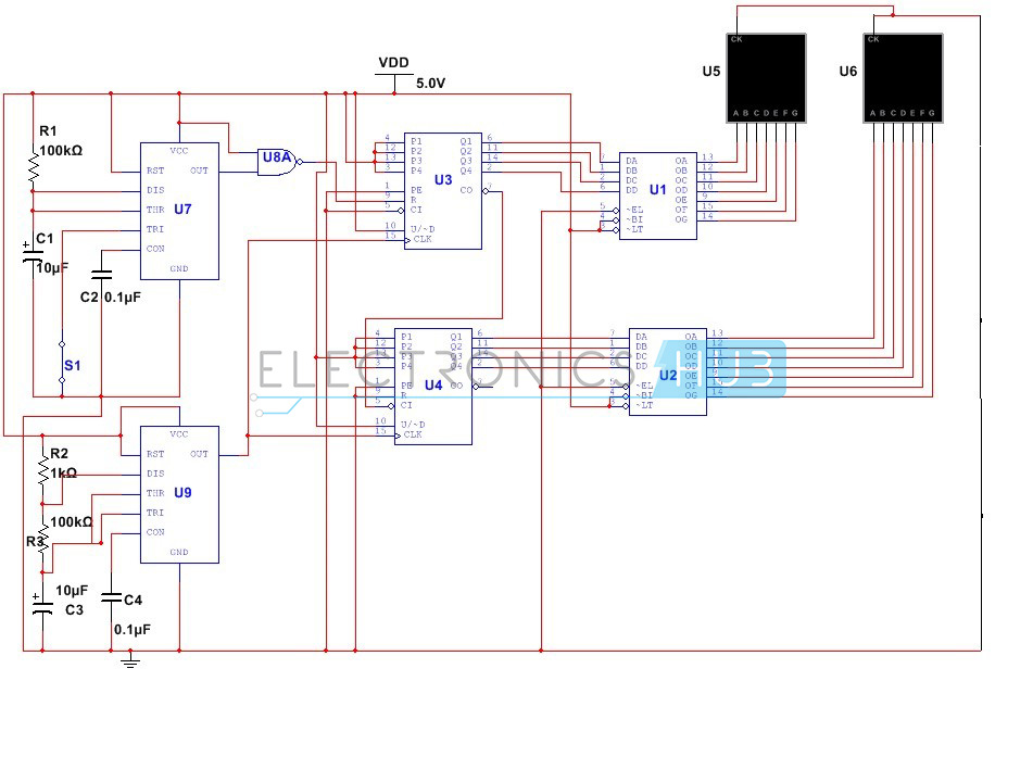 Circuit Diagram of Frequency Counter Frequency Counter Circuit Design:The primary requirement in our circuit is to generate an oscillating signal with a duty cycle of about 99% such that the time low value is less than the time high value of the output signal. Since duty cycle depends only on the value of the threshold and discharge resistors, it can be adjusted by selecting the proper values of resistors. The duty cycle is given by D = (Ra+Rb)/(Ra+2Rb) Substituting the value of D to be 0.99, we get the value of Ra to be 98 times the value of Rb. Thus selecting a value of 100 Ohms for Rb and 9.8k for Ra. Practically the value of 10k is chosen for Ra. Another requirement is to design a monostable multivibrator using 555 Timer. This circuit is designed to generate an output signal for duration of 1 sec. Since the time period of the output signal is equal to 1.1 times the product of R and C, (where R is the resistor between the discharge and Vcc pins, C is the capacitance between discharge pin and ground). Selecting a value of 100K for R, we calculate C to be about 9.09uF. Here we select 100K resistor and a 10uF capacitor. Next step of designing is the design of the counter circuit. Here our requirement is the measurement of frequency till 99Hz. We achieve this by synchronous cascading of two counter ICs – 4510. The clock pin of both ICs are connected to the output of the Timer 1 and the carry out pin of IC1 is connected to the carry in pin of IC 2. Since ICs 4510 do not have any in built display decoder, we require display decoder IC – CD4511 for each IC. The output pins of both decoder ICs are connected to the 7 segment display. Since our other requirement is to count the number of pulses for one second, we have to design a combinational circuit using another NAND gate whose inputs are connected to the output pin of Timer2 and Vcc. The output signal is connected to the reset pin of the counter IC1.
Frequency Counter Circuit Operation:The circuit commences to operate once switch S1 is in closed position. Based on the selected value of electrolyte capacitor, the 555 Timer produces an output signal whose frequency depends upon the value of the capacitor. This signal is fed as clock signal to the counter IC1. As long as reset pin of counter IC is at low logic low the counter will proceed it's counting. This is turn depends upon the time for which the reset pin is held at logic low level. Since the output pin of NOR gate IC is connected to the reset pin of IC1, a logic high signal at one of the inputs ensures a low signal at the reset pin. In other words, as long as the Timer1 generates a high output signal, the reset pin continues to be at low logic level and the counter continues its operation. However in case the count value reaches 9, the second counter comes into action and increases its count by 1. This whole process repeats until the Timer1 stops generating signal after a set time period and the output of the NOR gate is at logic high level, thus causing the counter IC1 to reset. The counts are displayed on the 7 segment displays connected directly to the counter ICs. The value of the count displayed shows the approximate count of number of cycles per second or frequency of the output signal. Limitations of this Circuit:
The post Frequency Counter Circuit appeared first on Electronics Hub. | ||||||||||||||||||||||||||||||||||||||||||||||||||||||||||||||||||||||||||||||||||||||||||||||||||||||||||||||
| Stepper Motor Control using 8051 Microcontroller Posted: 01 Jul 2014 03:10 AM PDT A stepper motor is a brushless and synchronous motor which divides the complete rotation into number of steps. Each stepper motor will have some fixed step angle and motor rotates at this angle. Here in this article, interfacing of stepper to 8051 and ULN 2003 is explained. Stepper Motor Control using Microcontroller Circuit Principle:The main principle of this circuit is to rotate the stepper motor step wise at a particular step angle. The ULN2003 IC is used to drive the stepper motor as the controller cannot provide current required by the motor.
Stepper Motor Control using 8051 Microcontroller Circuit Diagram: Circuit Diagram of Stepper Motor Control using AT89C51 Microcontroller Circuit Components:
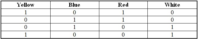
Stepper Motor Control using 8051 Microcontroller Circuit Design:The circuit consists of AT89C51 microcontroller, ULN2003A, Motor. AT89c51 is low power, high-performance, CMOS 8bit, 8051 family microcontroller. It has 32 programmable I/O lines. It has 4K bytes of Flash programmable and erasable memory. An external crystal oscillator is connected at the 18 and 19 pins of the microcontroller. Motor is connected to the port2 of the microcontroller through a driver IC. The ULN2003A is a current driver IC. It is used to drive the current of the stepper motor as it requires more than 60mA of current. It is an array of Darlington pairs. It consists of seven pairs of Darlington arrays with common emitter. The IC consists of 16 pins in which 7 are input pins, 7 are output pins and remaining are VCC and Ground. The first four input pins are connected to the microcontroller. In the same way, four output pins are connected to the stepper motor. Stepper motor has 6 pins. In these six pins, 2 pins are connected to the supply of 12V and the remaining are connected to the output of the stepper motor. Stepper rotates at a given step angle. Each step in rotation is a fraction of full cycle. This depends on the mechanical parts and the driving method. Similar to all the motors, stepper motors will have stator and rotor. Rotor has permanent magnet and stator has coil. The basic stepper motor has 4 coils with 90 degrees rotation step. These four coils are activated in the cyclic order. The below figure shows you the direction of rotation of the shaft. There are different methods to drive a stepper motor. Some of these are explained below. Full Step Drive: In this method two coils are energized at a time. Thus, here two opposite coils are excited at a time. Half Step Drive: In this method coils are energized alternatively. Thus it rotates with half step angle. In this method, two coils can be energized at a time or single coil can be energized. Thus it increases the number of rotations per cycle. It is shown in the below figure.
How to Operate this Stepper Motor Driver Circuit?
Stepper Motor Controller Circuit Advantages:
Stepper Motor Controller Circuit Applications:
The post Stepper Motor Control using 8051 Microcontroller appeared first on Electronics Hub. |
| You are subscribed to email updates from Electronics Hub To stop receiving these emails, you may unsubscribe now. | Email delivery powered by Google |
| Google Inc., 20 West Kinzie, Chicago IL USA 60610 | |


