
EEE, ECE & IE Project Updates
EEE, ECE & IE Project Updates |  |
| Ding Dong Sound Generator Circuit Posted: 19 Jun 2014 01:01 AM PDT Nowadays, door bells are very common in every house. We daily observe different types of door bells are available in the market and they produce different types of music depending on their functionality. One can design their own door bell using simple electronic components. This article explains a simple circuit that produces "ding dong" sound using 555 timer. Ding Dong Bell Sound Generator Circuit Principle:This circuit mainly consists of two 555 timer ICs. First timer IC is operated in astable mode and the frequency of the second is modulated by the first timer. For that, output pin of first IC is connected to the 5th pin of second IC. The first timer IC is operated at a frequency of 1Hz. Astable mode is a free running mode of the 555 timer IC. The 555 timer IC can be operated at required frequency by tuning the RC circuit. In astable mode, no external triggering is required. This has no stable state. Ding Dong Bell Sound Generator Circuit Diagram: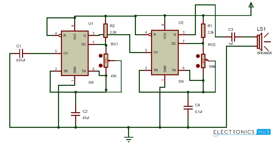 Circuit Diagram of Ding Dong Sound Generator Circuit Components:
Ding Dong Bell Sound Generator Circuit Design:The circuit consists of two 555 timer ICs arranged as shown in the circuit diagram. The first timer IC is connected in astable mode to produce pulse of frequency 1Hz. The 4th and 8th pins are shorted and connected to the resistor of 2.2K whose other end is connected to the pin of the timer IC. Sixth and seventh pins are connected to the variable resistor. Sixth and second pins are shorted and connected to the ground of 9v through a capacitor of 47uf. Fifth pin is connected to the ground through a capacitor of 0.01uf. First pin of the IC is connected to the ground.
The output pin of the first IC is connected to the control pin i.e. Fifth pin of the second IC. The second IC is also operated in astable mode again. 4th and 8th pins are shorted and connected to resistor of 2.2 k ohms whose other end is connected to the seventh pin of the IC. A variable resistor 100K is connected between sixth and seventh pins of the IC. Sixth pin and second pin are shorted and connected to the ground through a capacitor of 0.1uf. First pin is directly connected to the ground of 9v.Output pin of the IC is connected to the speaker through a capacitor of 1uf. How Ding Dong Sound Generator Circuit works?
Ding Dong Bell Sound Generator Circuit Applications:
Ding Dong Bell Circuit Limitations:
The post Ding Dong Sound Generator Circuit appeared first on Electronics Hub. |
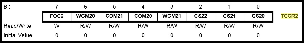
| PWM Based DC Motor Speed Control using Microcontroller Posted: 18 Jun 2014 11:36 PM PDT In many applications, it is important to control the speed of DC motor where precision and protection are essence. Here we will use a technique called PWM (pulse width modulation) to control the speed of DC motor. We can achieve speed control of DC motor using mechanical or electrical techniques but they require large size hardware to implement but Microcontroller based system provides easy way to control the speed of DC motor. Earlier, we have already seen how to control the speed of DC motor using PWM without Microcontroller. Here we do the same experiment by using a microcontroller. For that purpose, here we will use ATmega8 controller to produce PWM wave. By varying the width of this PWM wave, we can control the speed of DC motor. In ATmega8 controller, timer1 and timer2 have PWM mode. In this article we will see how to control the speed of DC motor using timer2 PWM mode. PWM Based DC Motor Speed Control using Microcontroller Circuit Principle:The heart of this project is ATmega8 controller. These controllers consist of 2 PWM modes. Now we will see how to generate PWM wave using timer2 PWM mode. Before writing the program to the PWM mode we need to know the register description of all the registers that are used for PWM mode. TCCR2 (Timer Counter Control Register): In Timer 2, we have different modes like CTC mode, normal mode, phase correct PWM mode, Fast PWM mode, etc. Among all of these modes, we have to select Fast PWM mode. From the above figure, it is clear that For Fast PWM mode, WGM21=1 WGM20=1 To select PWM mode TCCR2 |= (1<<WGM21)| (1<<WGM20); Again in PWM mode we have two modes one INVERTING and other is NON – INVERTING.
After that we have to select prescaler value. CS22 CS21 CS20 Description 0 0 0 No clock source 0 0 1 clk/1 0 1 0 clk/8 0 1 1 clk/32 1 0 0 clk/64 1 0 1 clk/128 1 1 0 clk/256 1 1 0 clk/1024
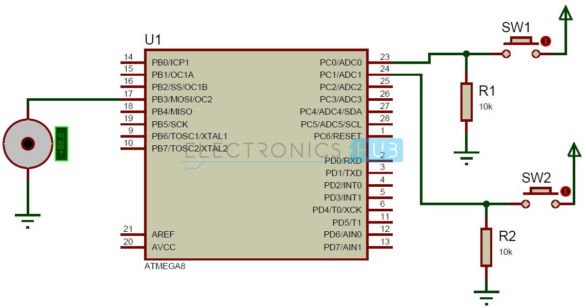
CS22=0 CS21=1 CS20=0 OCR2 (Output Compare Register): OCR2 register contains an 8 bit value that is continuously compared with counter value. PWM Program: void pwm ( ) { OCR2=128; TCCR2 |= (1 << COM21); // set none-inverting mode TCCR2 |= (1 << WGM21) | (1 << WGM20) // set fast PWM Mode TCCR2 |= (1 << CS21); // set prescaler to 8 and starts PWM } The above program runs the DC motor which is connected to PB3 with half speed. If you want to vary the speed vary the OCR2 register value. Circuit Diagram of PWM Based DC Motor Speed Control using Microcontroller:PWM based DC Motor Speed Control using Microcontroller Circuit Diagram Circuit Components:
PWM based DC Motor Speed Control using Microcontroller Circuit Design:The circuit consists of one Atmega8 controller, 2 pull down configuration switches and one DC motor. Generally we can interface switch to the micro controller in two configurations, one pull up configuration and other is pull down configuration. Pull up configuration: In pull up configuration initially microcontroller pin is pulled to LOGIC 1. When button is pressed microcontroller pin receives LOGIC 0 Pull down configuration: In pull down configuration initially microcontroller pin pulled to LOGIC 0. When button is pressed controller pin receives LOGIC 1. In our circuit we are using pull down configuration so we need to check for logic 1 in order to know weather the button is pressed or not. DC Motor: motor has two terminals. We have to connect one of the motor terminal to the controller pin and other to the ground. In this project motor runs with full speed when button sw1 is pressed and motor runs with half speed when sw2 button is pressed. How to Operate PWM based DC Motor Speed Control Circuit using Microcontroller?
PWM Based DC Motor Speed Control System Advantages:
PWM Based DC Motor Speed Control System Applications:
The post PWM Based DC Motor Speed Control using Microcontroller appeared first on Electronics Hub. |

| You are subscribed to email updates from Electronics Hub To stop receiving these emails, you may unsubscribe now. | Email delivery powered by Google |
| Google Inc., 20 West Kinzie, Chicago IL USA 60610 | |


